
Knowledge center: What is LCD TV ?and what is TFT LCD Displays
History of TFT LCD
Liquid crystal was found by the Austrian botanist Fredreich Rheinizer in 1888. "Liquid crystal" is not robust or Liquid (an illustration is lathery water).
In the middle of 1960s, researchers demonstrated that Liquid crystals when animated by an outside electrical charge could change the properties of light passing through the crystals.
The early models (late 1960s) were excessively precarious for large scale manufacturing. Anyway the greater part of that changed when a British scientist proposed a steady, liquid crystal material (biphenyl).
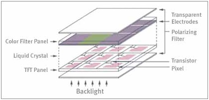
Today color LCD TVs and LCD Monitors have a sandwich-like structure
What is TFT LCD?
TFT LCD - Thin Film Transistor Liquid Crystal Display, has a sandwich-like structure with liquid crystal filled between two glass plates.
TFT Glass has the same number of Tfts as the quantity of pixels showed, while a Color Filter Glass has color channel which creates color. Liquid crystals move as per the distinction in voltage between the Color Filter Glass and the TFT Glass. The measure of light supplied by Back Light is controlled by the measure of development of the fluid crystals in such a route as to produce color!
TFT LCD - Electronic Aspects of LCD Tvs and LCD Monitors
Electronic Aspects of AMLCDs
The most well-known LCDs being used today depend on picture components, or pixels, framed by liquid-crystal cells that alter the polarization course of light passing through them because of an electrical voltage.
As the polarization bearing changes, pretty much of the light has the capacity pass through a polarizing layer on the substance of the presentation. Change the voltage, and the measure of light is changed.
There are two approaches to create a liquid-crystal picture with such cells: the fragment driving system and the lattice driving strategy.
The segment driving method displays characters and pictures with cells characterized by designed terminals.
The lattice driving system showcases characters and pictures in sets of dots!
Immediate versus multiplex driving of LCD Tvs.
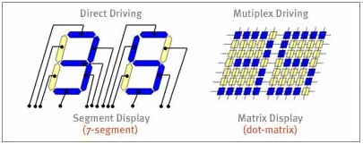
The segment drive strategy is utilized for straightforward displays, for example, those in number crunchers, while the dot-matrix drive technique is utilized for high-resolution displays, for example, those in portable computers and TFT monitors.
Two sorts of drive ways are utilized for matrix displays. In the static, or immediate, drive system, every pixel is exclusively wired to a driver. This is a straightforward driving technique, however, as the quantity of pixels is expanded, the wiring gets to be extremely intricate. An option strategy is the multiplex drive technique, in which the pixels are orchestrated and wired in a matrix group.
To drive the pixels of a dot-matrix LCD, a voltage can be connected at the crossing points of particular vertical sign terminals and particular flat checking cathodes. This strategy includes driving a few pixels in the meantime by time-division in a pulse drive. Accordingly, it is additionally called a multiplex, or dynamic, drive technique.
Detached and Active Matrix Lcds
There are two sorts of dot-matrix Lcds.
Passive-matrix versus active-matrix driving of LCD Monitors.
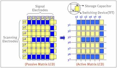
In passive-matrix Lcds there are no exchanging gadgets, and each pixel is addressed for more than one frame time. The viable voltage applied to the LC must average the signal voltage beats over several frame times, which brings about a moderate reaction time of greater than 150 msec and a decrease of the maximum contrast ratio. The addressing of a PMLCD also delivers a sort of crosstalk that creates smeared images because non-chose pixels are determined through a secondary signal-voltage path. In active-matrix Lcds, then again, an exchanging gadget and a storage capacitor are integrated at the each cross purpose of the anodes.
The active addressing uproots the multiplexing limitations by incorporating an active exchanging component. In contrast to passive-matrix Lcds, Amlcds have no inalienable limitation in the quantity of scan lines, and they show less cross-talk issues. There are many sorts of AMLCD. For their integrated exchanging gadgets most utilize transistors made of kept dainty films, which are subsequently called thin film transistors!
The most well-known semiconducting layer is made of amorphous silicon (a-Si).
a-Si Tfts are amenable to large-area fabrication utilizing glass substrates as a part of a low-temperature (300°c to 400°c) methodology.
An alternative TFT innovation, polycrystalline silicon - or polysilicon or p-Si-is expensive to create and especially hard to fabricate when manufacturing large-area displays.
Nearly all TFT Lcds are made from a-Si because of the technology$$$s economy and maturity, however the electron portability of a p-Si TFT is one or two requests of magnitude greater than that of an a-Si TFT.
This makes the p-Si TFT a decent candidate for a TFT array containing integrated drivers, which is liable to be an attractive decision for small, high definition displays, for example, view discoverers and projection displays.
Structure of Color TFT LCD Tvs and LCD Monitors
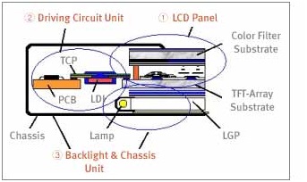
A TFT LCD module comprises of a TFT panel, driving-circuit unit, backlight framework, and assembly unit.
Structure of a color TFT LCD Panel
It is ordinarily used to display characters and graphic images when joined a host framework.
The TFT LCD panel comprises of a TFT-array substrate and a color-channel substrate.
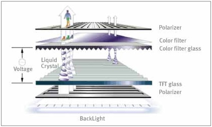
The vertical structure of a color TFT LCD panel.
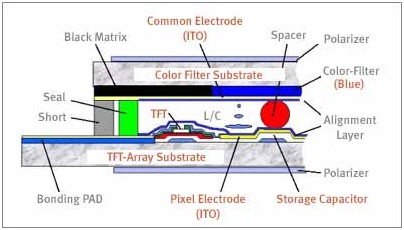
The TFT-array substrate contains the Tfts, storage capacitors, pixel anodes, and interconnect wiring. The color channel contains the black matrix and sap film containing three primary-color - red, green, and blue - colors or shades. The two glass substrates are assembled with a sealant, the gap between them is maintained by spacers, and LC material is infused into the gap between the substrates. Two sheets of polarizer film are attached to the external faces of the sandwich structured by the glass substrates! A set of holding pads are fabricated on each end of the gate and data-signal transport lines to attach LCD Driver IC chips
Driving Circuit Unit
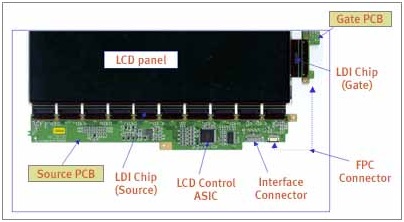
Driving an a-Si TFT LCD obliges a driving circuit unit comprising of a set of LCD driving IC chips and printed-circuit-boards
The assembly of LCD driving circuits.
A block diagram showing the driving of an LCD panel.
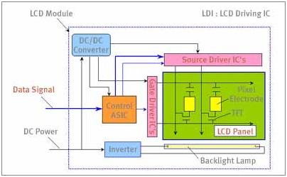
To diminish the foot shaped impression of the LCD module, the drive circuit unit can be placed on the backside of the LCD module by utilizing bowed Tape Carrier Packages and a tapered light-guide panel.
How TFT LCD Pixels Work
A TFT LCD panel contains a particular number of unit pixels regularly called sub pixels.
Each unit pixel has a TFT, a pixel cathode (It0), and a storage capacitor (Cs).
For example, a SVGA color TFT LCD panel has total of 800x3x600, or 1,440,000, unit pixels.
Each unit pixel is joined with one of the gate transport lines and one of the data transport lines in a 3mxn matrix format. The matrix is 2400x600 for SVGA.
Structure of a color TFT LCD panel.
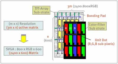
Because each unit pixel is associated through the matrix, each is individually addressable from the holding pads at the finishes of the lines and sections.
The performance of the TFT LCD is related to the configuration parameters of the unit pixel, i.e., the channel width W and the channel length L of the TFT, the overlap between TFT terminals, the sizes of the storage capacitor and pixel cathode, and the space between these components.
The configuration parameters associated with the black matrix, the transport lines, and the steering of the transport lines also set important performance constrains on the LCD.
In a TFT Lcds unit pixel, the liquid crystal layer on the ITO pixel cathode structures a capacitor whose counter anode is the regular terminal on the color-channel substrate.
Vertical structure of an unit pixel and its equivalent circuit
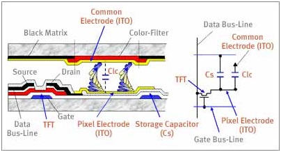
A storage capacitor and liquid-crystal capacitor are joined as a load on the TFT.
Applying a positive beat of about 20v peak-to-peak to a gate anode through a gate transport line turns the TFT on. Clc and Cs are charged and the voltage level on the pixel cathode climbs to the signal voltage level (+8 V) applied to the data transport line.
The voltage on the pixel anode is subjected to a level movement of DV coming about because of a parasitic capacitance between the gate and drain cathodes when the gate voltage turns from the ON to OFF state. After the level move, this charged state can be maintained as the gate voltage goes to -5 V, at which time the TFT turns off. The main capacity of the Cs is to maintain the voltage on the pixel anode until the following signal voltage is applied.
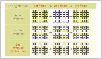
Liquid crystal must be determined with an alternating present to keep any deterioration of image quality coming about because of dc anxiety.
This is usually actualized with a frame-reversal drive strategy, in which the voltage applied to each pixel varies from frame to frame. On the off chance that the LC voltage changes unevenly between frames, the result would be a 30-Hz glint.
(One frame period is normally 1/60 of a second.) Other drive strategies are available that keep this glint issue.
Polarity-reversal driving strategies.
In an active-matrix panel, the gate and source cathodes are utilized on a shared basis, however each unit pixel is individually addressable by selecting the appropriate two contact pads at the finishes of the columns and sections.
Active addressing of a 3*3 matrix
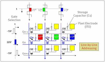
By scanning the gate transport lines sequentially, and by applying signal voltages to all source transport lines in a defined grouping, we can address all pixels! One consequence of all this is that the addressing of an AMLCD is carried out line by line.
Virtually all Amlcds are intended to create gray levels - intermediate shine levels between the brightest white and the darkest black an unit pixel can generate. There can be either a discrete quantities of levels -, for example, 8, 16, 64, or 256 - or a ceaseless gradation of levels, contingent upon the LDI.
The optical transmittance of a TN-mode LC changes consistently as a capacity of the applied voltage.
An analog LDI is capable of creating a consistent voltage signal so that a ceaseless range of gray levels can be displayed.
The digital LDI produces discrete voltage amplitudes, which allows on a discrete quantities of shades to be displayed. The quantity of gray levels is dictated by the quantity of data bits created by the digital driver.
Generating Colors
The color channel of a TFT LCD TV comprises of three primary colors :red, green, and blue , which are incorporated on the color-channel substrate.
How a LCD Panel produces colors.
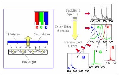
The components of this color channel line up balanced with the unit pixels on the TFT-array substrate.
Each pixel in a color LCD is subdivided into three sub pixels, where one set of RGB sub pixels is equal to one pixel!
Each sub pixel comprises of what we have been calling an unit pixel as yet...
Because the sub pixels are so small it is not possible recognize autonomously, the RGB components appear to the human eye as a mixture of the three colors!
Any color with a few qualifications can be delivered by blending these three primary colors.
The total number of display colors utilizing a n-bit LDI is given by 23n, because each sub pixel can generate 2n diverse transmittance levels.


